


Victor Orive, Mustafa Arslan, Mustafa Alkan and Beni Kohen show how a strong architectural idea survives complexity on the Central Bank of Iraq: define the non-negotiable intent, rationalise geometry, preserve data from design to fabrication, test difficult conditions and keep architects, engineers and manufacturers in the same problem-solving loop.
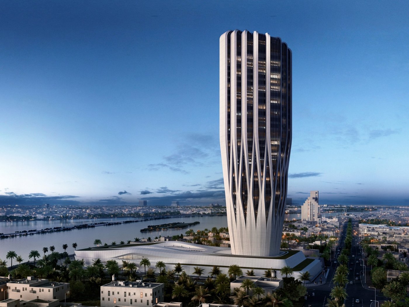
A rendering can make a complex façade appear inevitable. Construction exposes the opposite reality: every panel needs a name, every joint a hierarchy, every bracket a load path and every ambitious surface a method of manufacture, transport and installation. The Central Bank of Iraq brings architecture, engineering and manufacturing into one continuous delivery problem. Victor Orive of Zaha Hadid Architects, Mustafa Arslan and Mustafa Alkan of Werner Sobek Istanbul, and Beni Kohen of Fibrobeton describe a 172-metre, approximately 90,000-square-metre institutional tower on the banks of the Tigris in Baghdad, an envelope intended to express solidity, stability and sustainability while meeting demanding climatic, security and construction conditions.
An exoskeleton shaped by institution and climate
The design process began in late 2010 with workshops to establish the brief. The client wanted a central bank that could represent the institution and the country over decades, not a short-lived image of the moment. Zaha Hadid Architects explored an exoskeleton in which the structure becomes the façade. The concept carried several responsibilities at once. Visually, it could communicate strength and stability. Environmentally, its depth could shade the tower’s glazing in Baghdad’s intense sun. Programmatically, it had to accommodate secure and separate circulation while presenting a coherent public identity.
Early studies were symmetrical, reinforcing an institutional presence. Solar analysis complicated that ideal. A perfectly symmetrical envelope could not respond equally well to east, west, north and south. The design therefore evolved into an apparently balanced but environmentally asymmetric system: open toward northern views and progressively more protective toward solar exposure. By detailed design, the tower used a single-skin approach on the north and east and deeper or double-skin conditions on the south and west. Solid portions of the façade were oriented in response to solar angles. The geometry was not presented as arbitrary formalism; it was the result of context, weather, programme and the desire to retain an unmistakable architectural identity.
From tower to podium: one language in two directions
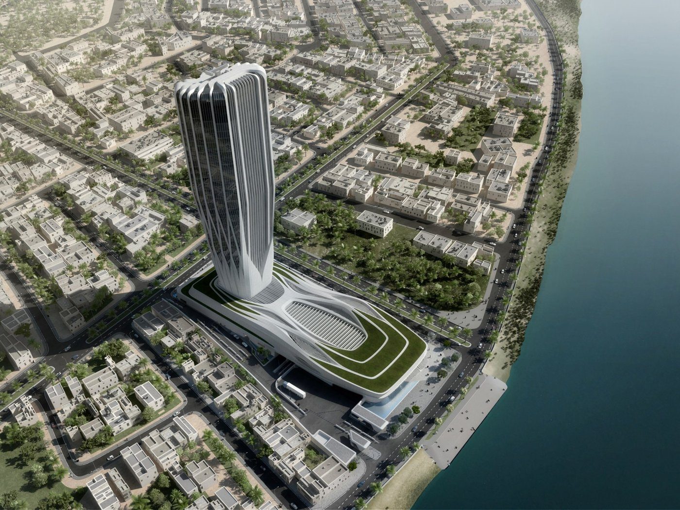
The tower was moved back from the river as the design developed, allowing a podium to emerge between it and the water. The podium uses the same language of branching and rotating elements, but lays it across the site as a landscape-like volume, almost a shadow of the tower. This move established a dialogue between vertical and horizontal architecture. It also created what the team calls a fifth façade, visible from the tower atrium. Different public, staff and VIP entrances could be organised within the podium while the exoskeleton maintained a common institutional language.
The design timeline extended from concept in 2010–2011 through schematic design, detailed design, construction documentation and tender in 2015. DAAX received the main contract in 2017, and site construction began in 2019. The long duration made the quality of the tender information and the adaptability of the team especially important.
Rationalise everything that does not need to be unique
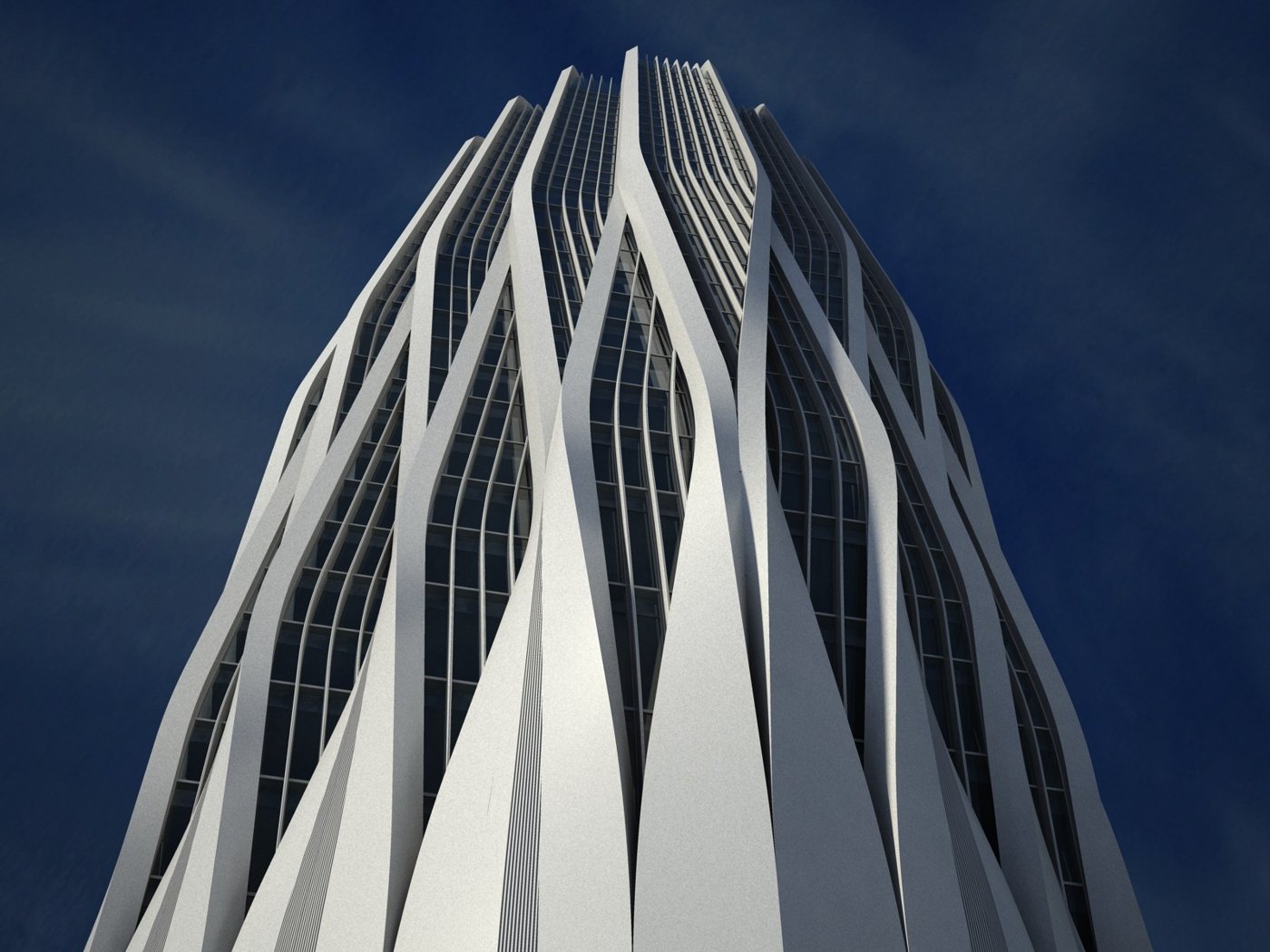
Complex façades are often accused of being impossible to repeat. The Central Bank team took the opposite approach: allow complexity where it carries architectural or environmental value, and maximise repetition everywhere else. Curvature was limited to the zones where it mattered. Symmetry, rotation and repeated floor conditions were used to create panel families. By the end of construction documentation, every cladding panel and every glass pane had been individually named and drawn. Joints were arranged in a deliberate hierarchy rather than allowed to appear wherever production convenience dictated.
This discipline protected the reading of the building as a solid form. Orive emphasised the importance of avoiding exposed corner joints: a joint on the corner would make the exoskeleton read as tiled cladding rather than as a continuous structural body. Corner pieces therefore became larger and more demanding, but they preserved the intended mass and shadow. Rationalisation did not eliminate variety. Fibrobeton reported more than 11,000 pieces and more than 8,000 different piece conditions across the architectural precast scope, alongside substantial quantities of exterior high-performance concrete and interior GFRC. Repetition still existed, particularly across upper floors and through rotated counterparts, but it had to be identified through a rigorous digital classification rather than assumed from appearance.
Material choice as a design and security decision
The team evaluated precast concrete, GRC and higher-performance concrete alternatives for the exoskeleton. Conventional precast was considered too heavy and likely to impose a visible grid. The selected high-performance concrete solution was preferred for its tactile quality, lower porosity, cleaning behaviour in a dusty environment and deformation characteristics under security-related loads. Material selection therefore affected more than weight or finish. It influenced panel size, corner continuity, support design, weathering, maintenance, security behaviour and the perceived solidity of the institution.
The deep fins had a clear environmental role. With office floor-to-floor heights of around 4.2 metres and large glazed areas, the team needed to admit useful daylight while controlling direct solar gain. Baghdad’s clear blue sky produces different daylight conditions from the cloudy climate familiar to many London-based consultants. Fin depth and orientation had to be studied for the actual location, not transferred from a generic daylight assumption.
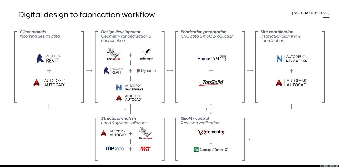
The production team described a digital workflow moving through multiple platforms, including Revit, Rhino and fabrication software. The central risk was data loss: geometry, naming, embed positions and revisions had to remain coordinated as the model moved from architectural rationalisation to engineering and machine-ready information. A successful digital-to-fabrication workflow requires more than interoperable file formats. It needs a shared classification system, agreed model ownership, controlled revision exchange and teams capable of reading the design logic, not just importing surfaces. This was particularly important for fins and pieces with integrated steel anchors. Some elements required closed moulds and carefully sequenced casting. Flexible mould components were used to accommodate shrinkage around substantial embedded steel and reduce the risk of surface cracking. Weight reduction in the concrete element could not compromise the stiffness and tolerances needed for anchorage and movement.
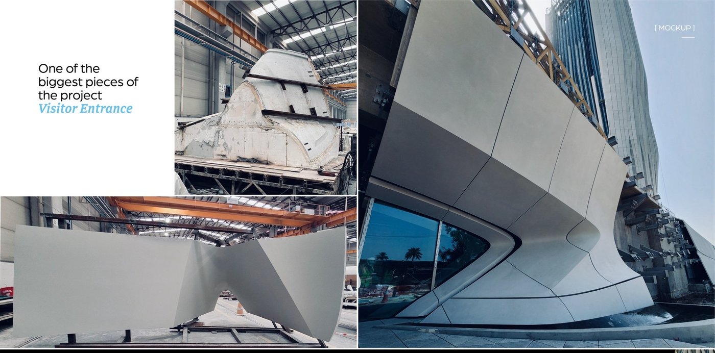
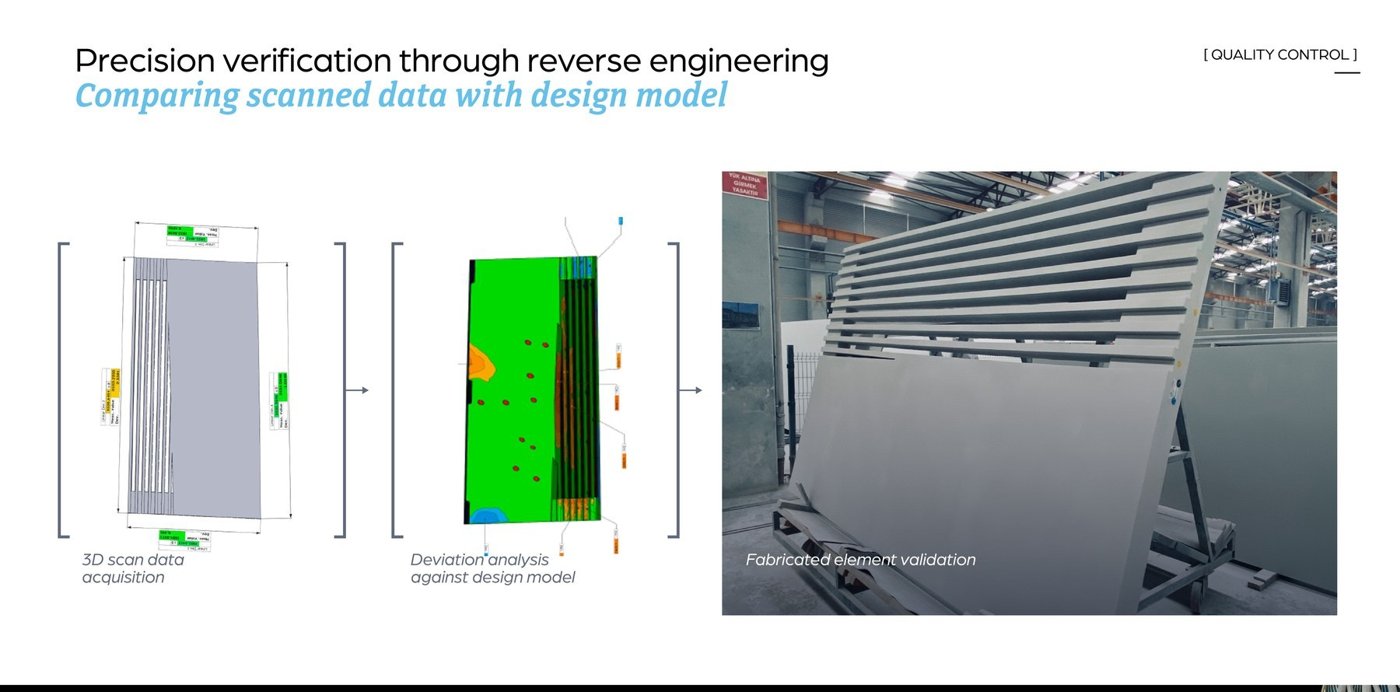
Prototypes and mock-ups allowed teams to test appearance, joints, finish, anchorage and installation before full production. Once construction advanced, precision verification moved in both directions. Digital information guided manufacturing, while scanning and reverse engineering captured real site conditions so that subsequent pieces and interfaces could be checked against what had actually been built. That feedback loop is crucial on a long-running project. Primary structure, secondary steel, concrete production and survey tolerances accumulate. A theoretically perfect panel can still fail to fit if the supporting work is not measured and incorporated into the installation model.
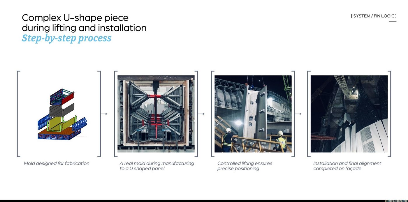
The lifting sequence for a complex U-shaped piece makes the final challenge visible. A panel must not only be manufacturable; it must be removable from its mould, stored, transported, rigged, rotated through space, installed without damage and replaceable in principle. Installation geometry belongs in the design model from the beginning.
The project team rejected the familiar myth that architects draw an impossible floating object and engineers later make it stand up. The original design process included structure, MEP, façade, security and other disciplines. The construction team still proposed changes, as every real project requires, but deviations were assessed against a clear architectural intent. That clarity created room for collaboration. Details did not need to be reproduced literally when a better fabrication or installation solution was available; they did need to preserve the essential appearance, performance and hierarchy of the façade. The project team described days of joint work on individual brackets because those supports were necessary to retain the geometry without introducing visible compromises.
Lessons for complex-envelope delivery
What the project offers other landmark façades is less a checklist than an order of operations. The non-negotiable design intent comes first, stated in terms of mass, joints, shadow, environmental response and institutional meaning. Geometry is rationalised early and every production unit named consistently. Climate and programme are allowed to generate asymmetry even where the composition has to appear balanced. Material and support strategy are chosen together, because a finish settled before the loads, embeds and installation are understood is a finish that will be changed. And the digital chain from design model through fabrication and survey stays under control throughout.
What gets prototyped matters as much as what gets drawn: the corner, the fin and the lifting condition rather than a convenient flat bay. Site scanning and reverse engineering close the gap between the model and the construction, and the fabricator’s knowledge is treated as design intelligence rather than a threat to the core idea. The Central Bank of Iraq demonstrates that the opposite of complexity is not simplicity but clarity – about what must remain, where repetition is possible, how information moves, and who is responsible for each interface.