


Brian Davie treats airtightness as a continuous building-envelope problem rather than a membrane specification. The 2024 IECC makes that systems view more explicit by pushing testing, inspection and thermal-bridge decisions further into design documentation.
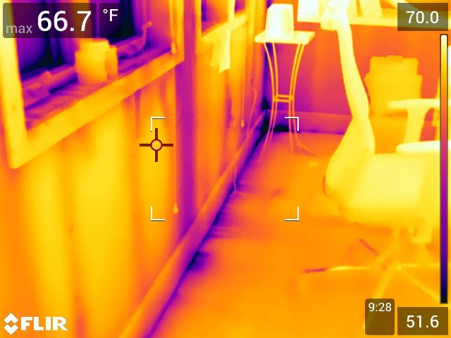
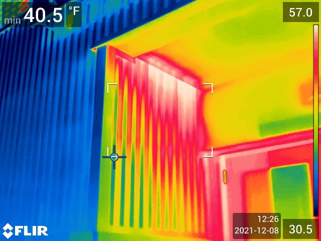
A thermal image of cold air entering beneath a wall is an effective reminder that airtightness failures rarely announce themselves as a defective product. Davie's starting point is that an air barrier is not the sheet, fluid-applied coating or board that happens to carry the label. It is the continuous system enclosing conditioned space, including roof, wall, foundation, fenestration, doors and every transition between them. The distinction matters because a project can specify excellent individual materials and still leak badly at the points where trades, planes or assemblies meet. Air performance therefore depends on continuity being designed, communicated, installed and verified as one coordinated layer.
Davie places air leakage high on the list of enclosure issues because its effects propagate through several building systems at once. In his experience with energy modelling and performance verification, uncontrolled air movement is one of the largest envelope-related influences on energy use. It also affects drafts and occupant comfort, increases mechanical demand and can create moisture and condensation risks when air carries vapour through assemblies. That makes airtightness less a specialist detail than a building-wide performance condition. The 2024 International Energy Conservation Code, as Davie interprets it for practice, reinforces that shift by connecting documentation, testing and inspection more directly to the design phase.
Testing has to be designed before it can be performed
One of the most practical changes is the expectation that construction documents identify how compliance will be verified. Davie highlighted requirements to show where air-leakage testing will or will not be performed and, where testing is not used, to provide a plan for field inspections. That is a significant workflow change because verification is often treated as a construction-stage decision, long after the drawings have established the enclosure geometry. If the testing strategy is known earlier, the design team can define test zones, anticipate temporary separations, coordinate access and make sure the air-control line can actually be traced through plans, sections and details.
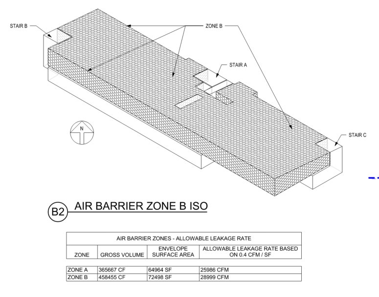
Whole-building testing is the baseline approach for many commercial and single-tenant buildings. The method pressurises or depressurises the completed enclosure and measures total leakage through architectural components. In practice, that means the test cannot happen meaningfully until thresholds, weather seals, doors, windows and other late-stage items are sufficiently complete. Large buildings can also require substantial fan capacity, so Davie showed how test areas may be divided into manageable zones. These are not merely logistical questions. A zone boundary that is easy to draw on a diagram may be difficult to establish in the physical building unless temporary conditions and permanent compartment lines are understood early.
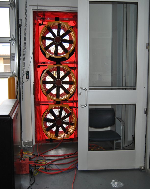
Unit-level testing introduces another layer of difficulty. Apartments, hotel rooms, dormitories and other overnight-occupancy spaces are measured as small pressure zones, and Davie stresses that smaller volumes are less forgiving. The test boundary includes not only the exterior wall but also demising walls, corridor interfaces and penetrations through partitions that may never have been thought of as façade details. Electrical outlets, switches and service penetrations can become significant leakage paths because the compartment is being tested as a whole. The result is a useful inversion of traditional responsibilities: the building enclosure team has to think beyond the exterior elevation, and interior trades become part of the airtightness strategy.
Small rooms expose large coordination gaps
Davie illustrated the point with a Colorado School of Mines dormitory where 44 units across six floors were tested. The team eventually achieved passing results, but studio units proved particularly challenging because an exposed deck condition left open air pathways into exterior or demising walls. Those paths had to be identified and sealed with the contractor. The lesson is not that this condition is unusual; it is that testing converts invisible coordination assumptions into measurable failures. When a space is small, a modest opening represents a larger proportion of the permitted leakage, so construction tolerance and trade interfaces become much more consequential.
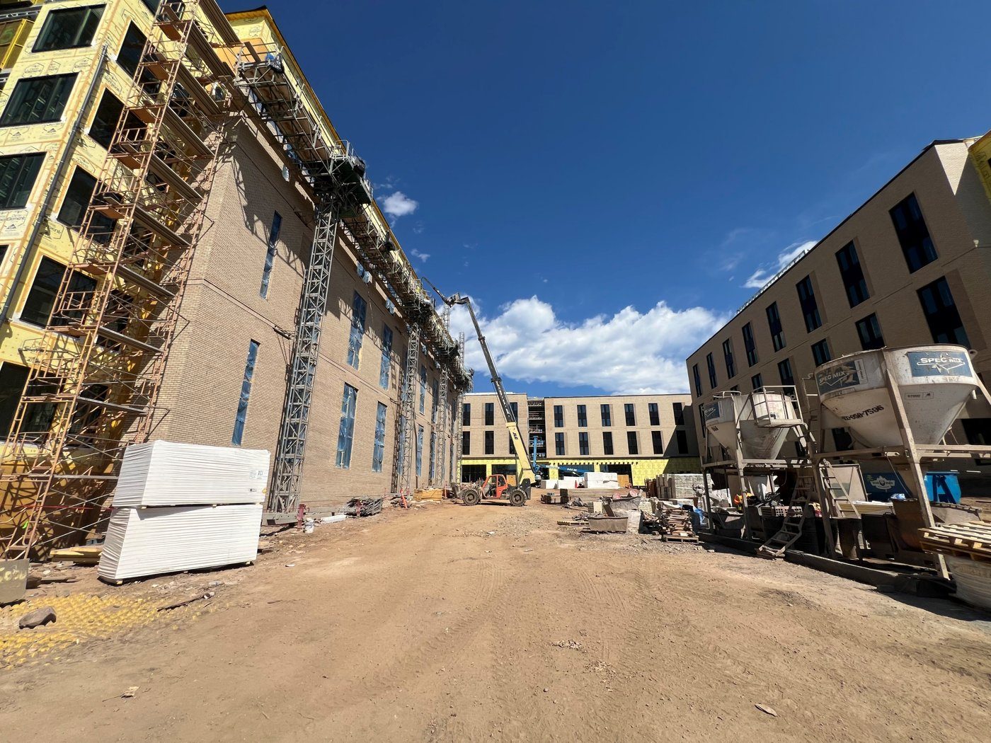
Where testing is not applicable, Davie describes a verification route that begins to resemble enclosure commissioning: document review, observations while the air barrier is still exposed, tracking of deficiencies, correction and a final report or statement of compliance. The crucial phrase is "while the air barrier is accessible". Once cladding, ceilings or interior finishes conceal a discontinuity, diagnosis becomes slower and remediation more destructive. The number and timing of inspections therefore have to follow construction sequencing. A large façade closing rapidly may need more frequent observation than a small project, not because the material is different but because the opportunity to see the work disappears faster.
Thermal bridges move into the same conversation
The 2024 code cycle also brings explicit attention to thermal bridging. Davie noted that the dedicated requirements include exceptions - including a broad climate-zone exception he discussed for zones 0 through 3 - but where they apply they affect familiar details such as balconies, cladding supports, structural beams and columns, fenestration placement and parapets. The principle is similar to airtightness: continuity of the thermal layer matters most at transitions. A wall with continuous exterior insulation can still be compromised by conductive steel passing through it, or by a parapet that allows the insulation line to stop before reconnecting with the roof.
Parapets are a useful example because good practice and minimum construction have not always aligned. Davie points out that wrapping continuous insulation over and behind a parapet to meet the roof insulation can add a meaningful quantity of material and cost, especially on tall parapets. Similar consequences follow from requirements governing where a window's thermal break sits relative to continuous wall insulation. These details are small in elevation but large in aggregate. If they are considered only after pricing or submittals, teams are forced into local fixes; if they are resolved early, the thermal, air and water-control layers can be coordinated as one section rather than three unrelated specifications.
The recurring risk, for Davie, is not a lack of capable products. It is communication failure between drawings, trades and construction stages. A two-dimensional detail can look complete while the actual three-dimensional transition around a corner, roof edge or foundation contains a gap. Late changes can break a previously continuous strategy. Weak QA/QC allows one trade to cover another's unfinished interface. And discovering leakage only during final testing can turn a correctable detail into demolition. Spray foam is not a universal rescue method; some failures require access to the actual control layer.
His practical prescription is straightforward: define the air barrier early, draw it continuously, decide how it will be verified and keep the testing logic visible as the project develops. Kick-off coordination, design peer review, mock-ups and construction observations are not separate layers of bureaucracy if they are all answering the same question: does the enclosure work as a continuous system? The 2024 IECC makes that question harder to postpone. That is useful pressure. Airtightness succeeds when the performance boundary is treated as a design object from the beginning rather than a test result expected at the end.